LEARN TO GET THE MOST FROM THE SYSTEM
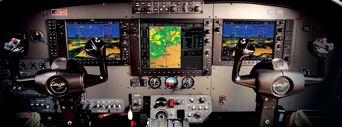
With a rectangular computer display replacing that well-known pack of six round flight instruments, and data presentation that differs considerably from the analog format, it’s no surprise that crews might feel lost, even uncomfortable, flying behind a panel with little resemblance to its former self.
WHAT’S REALLY NEW ABOUT GLASS COCKPITS?
Other than the information they portray, pretty much everything is new: how they work, what drives them, how they share software and display failure modes, and, most significantly, how they actually look.
Pilots transitioning to the glass environment need to have confidence in their understanding of the systems and information.
KEY COMPONENTS OF GLASS-PANEL TRAINING
SYSTEMS OVERVIEW
Power sources: How the panel receives and uses power, including standby or back-up systems, their capacities and a method to match load to generating limits in any electrical failure
Sensor(s): Failure modes and knowing the impact of failures, which are critical in the event of either a failed Attitude and Heading Reference System (AHARS) or ADAHARS (an AHARS with integral air-data sensing)
Reversionary Modes: Comfort and competency using built-in back-up functions so crew can move data from a failed primary flight display to a functional screen, such as the multifunction display.
Air-Data: Knowledge of the system’s connections, with both main and standby instrument clusters; pitot/static system plumbing gives air-data sensors contact with the atmosphere.
Standby systems: The best stand-by solutions closely resemble the look and function of the main systems they back up, but should run as independently as possible; separate power in the form of a back-up battery is best, compared to one wholly dependent on the main electrical sources.
Flight-Control System architecture: Know whether the autopilot depends on the attitude sensors feeding the PFD, whether the flight-control system employ stand-alone sensors – and how to override a runaway flight-control system.
Programming: Controlling functions such as moving-map displays, alternate screens with traffic or weather, even simply using VHF radios, the GPS or other navigation sensors.
SCENARIO-BASED SIMULATOR TRAINING
Training starts with a VFR cross-country simulation. Learn to program pilot preferences and basic Direct-to navigation. There are many variations of what is displayed on the primary and multifunction displays. Learn how to configure the screens so that what is most important to you is easy to see without much knob turning.
If you are using an autopilot, you will learn to use the Vertical Speed, Flight Level Control, and Vertical NAV functions with Along Track Offset to program altitude changes and the start of your descent.
Engine management pages will get a review. Your instructor will explain the basics of the engine systems information display.
You can optionally get exposure to weather function such as Nexrad. There are many features that can do everything from draw surface maps on the MFD to bringing up METARs at stations along your route.
Finally, just about everything you need to know about your destination airport is a knob turn away, including frequencies, airport diagram, runways information, lighting, and approaches. You will get to know how to quickly access these pages so you feel comfortable in the airplane.
Having completed the ground training, we then take you for one or more flights in the airplane and let you experience the G1000 in flight to solidify the learning.
This program does not require approval under the Ontario Career Colleges Act, 2005.
At Genesis Flight College, we offer glass transition training courses at our Collingwood, Ontario location to students from all over Canada, including Collingwood, Toronto, Barrie, Aurora, Brampton, Caledon, Markham, Newmarket, Richmond Hill, Vaughan, and Mississauga, Ontario; Calgary and Edmonton, Alberta; and Victoria and Vancouver, British Columbia.
GLASS-PANEL COMPONENTS
G1000 PRIMARY FLIGHT DISPLAY (PFD)
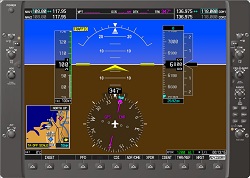
The primary flight display shows the basic flight instruments, such as the airspeed indicator, the altimeter, the heading indicator, and course deviation indicator. A small map called the “inset map” can be enabled in the corner. The buttons on the PFD are used to set the squawk code on the transponder. The PFD can also be used for entering and activating flight plans. The PFD also has a “reversionary mode” which is capable of displaying all information shown on the MFD (for example, engine gauges and navigational information). This capability is provided in case of an MFD failure.
G1000 MULTI-FUNCTION DISPLAY (MFD)
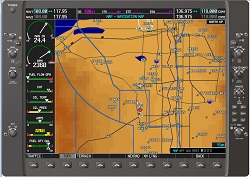
The MFD usually shows engine instrumentation and a moving map.
The multi-function display typically shows a moving map on the right side, and engine instrumentation on the left. Most of the other screens in the G1000 system are accessed by turning the knob on the lower right corner of the unit. Screens available from the MFD other than the map include the setup menus, information about nearest airports and NAVAIDs, Mode S traffic reports, terrain awareness, XM radio, flight plan programming, and GPS RAIM prediction.